The nation’s deteriorating highway infrastructure requires new computerized Non-Destructive Evaluation (NDE) test methods, which provide analytical data to establish maintenance demands. Applying new non-destructive tools, specifically designed to quantify the extent and number of defects in the infrastructure, will allow maintenance priority assessment and provide the knowledge necessary to establish resource-planning parameters for maintenance scheduling.
Concrete and Asphalt Bridge Deck Delamination
By: Gary Strahan – CEO, Infrared Cameras Inc – infraredcameras.com
The overall size of the camera system, cost size, and sensitivity have improved dramatically in the last few years. For example a quality (hand held) thermal imaging radiometer system and software had an average price of >$57,000.00 in 2000 and an average thermal sensitivity of .1 degree C or 100 millikelvin. In 2000 the cost of such a system was typically > $100,000.00. Average weight of one of the cameras itself was 6 to 15 pounds. Today a Bridge delamination detection system will cost <$20,000.00, the camera itself weighs less than 8 ounces, and has a thermal sensitivity of < .038 degrees C or 38 millikelvin. Numerous hand held cameras are available today for < $7000.00 and have better sensitivity than those systems manufactured in 2000. Most of these cameras utilize a microbolometer based sensor that detects electrical resistance across each pixel based on emitted radiation from the scene. There are currently four basic microbolometer arrays available commercially. They are as follows, 160 x 120, 384 x 288, 320 x 240, and 640 x 480. They are not all the same and vary by manufacturer. The definition of the term bolometer means resistor.
Thermal imaging systems are also currently being tested to find cracks in steel bridge structures under paint. These inspections are typically being conducted at night and in shaded areas. The small amount of friction created by the crack, from molecular movement is conducted to the surface of the paint and then radiated to the surface. This radiation then travels at the speed of light, 186,000 miles per second to the sensor in the thermal camera and is converted to an image we can then interpret. These inspections are more efficient when solar radiation is not introduced into the scene.
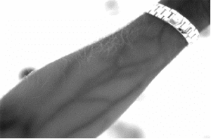
Figure 27-0 (below) shows an example of how blood veins in a human arm can be seen as radiation from the warm blood conducts energy to the cooler skin surface.
Thermal imaging cameras can only see and measure surface temperature. They do not see through walls or bridge decks. They simply see thermal differences at the surface of the object created by differences in thermal conductivity.
Our nation’s bridges account for a substantial component in highway infrastructure. In particular, the reinforced concrete decking used to construct these bridges is continuously being degraded due to normal traffic and environmental exposure. This degradation is exacerbated in climatic regions where de-icing chlorides are used and in coastal regions where bridges are exposed to high salt air concentrations.
The importance of a comprehensive bridge deck management program is well understood and, in fact, monitoring bridge conditions is a priority for federal and state transportation departments. Many methods have been applied to the inspection of bridge deck systems. These methods include coring of the pavement, conductivity tests, and pavement sounding using acoustical devices. Although reasonably successful, these techniques are generally tedious and time consuming. Many of these traditional inspection methods, such as the chain method, rely on mechanical sounding techniques to detect delaminations within the deck structure. This method is labor intensive, time consuming, and operator dependent.
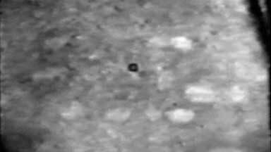
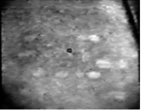
A study conducted by Clemena and McKeel as far back as 1977 demonstrated that thermography has significant advantages over conventional techniques in detecting bridge deck delaminations. There were several reasons cited within this study that suggest why thermography is preferred, for example the process requires shorter inspection time resulting in fewer or shorter lane closings, thus less impact on traffic flow. This study establishes thermography as a proven, rapid, non-destructive detection method with the added capability to delineate bridge deck delaminations. Figure 27-1 illustrates the image output provided by an infrared camera. This image presents several delaminations in a small area. The delamination is evident by the large contrast changes in the image. Not only can you detect where the delamination is located, you can also characterize its size and shape. This capability provides the basis for developing analytical tools to map and quantify defects within the bridge deck. Note: the black rectangle at the center of the image is a sensor graphic and not a thermal occurrence in the scene.
Infrared thermography has been used successfully in a wide variety of industrial, commercial, and environmental applications. These applications are well documented in trade publications, technical journals, and seminar proceedings. With particular relevance to this discussion however, thermography has steadily grown over the recent past to become a proven method for bridge deck inspection. The American Society For Testing And Materials (ASTM) has, in fact, developed a standard procedure for the bridge deck test process. ASTM Standard Test Method for Detecting Delaminations in Bridge Decks Using Infrared Thermography outlines an accepted and proven test method for bridge inspections.
Imaging, in general, has been successfully used for many years beginning with the introduction of the still photograph then the film movie camera and, most recently, video recording systems. All imaging cameras, whether they are visual systems or infrared, intercept and record electromagnetic radiation as it propagates through the atmosphere. A thermal infrared imaging camera is one that intercepts electromagnetic radiation in the form of heat energy as it radiates from an object. This heat energy is absorbed by an infrared sensor, which produces an electronic signal. If enough sensors are available to encompass an entire scene, an image can be generated.
With any visual system we can detect an object within a scene because that object looks different than its surroundings. With infrared imaging, we can detect an object within a scene because the thermal characteristics, or signature, of that object differs from its surroundings. A bridge deck can be described as a multi-layered, semi-infinite solid in which time dependent heat conduction occurs along a one-dimensional path. This path is based on the thermal conduction properties of the bridge material and the boundary conditions established by the surface environmental input. The top surface is subject to varying thermal inputs from solar radiation, convection forces, and thermal radiation exchanges.
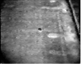
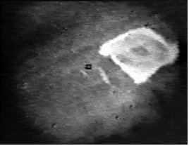
Corrosion of embedded steel reinforcement within a bridge deck is the main source of deck delamination. As the reinforcement material corrodes, it expands and creates a subsurface fracture within the concrete. When this delamination occurs in a bridge section, a disruption in thermal conduction properties of the material occurs at that local site. As a result, the normal flow of energy along the thermal path is altered relative to the solid deck structure. During a daytime infrared inspection, these delaminations appear as white or “hot” areas on a gray or “cooler” deck background.
Although thermography has proven itself to be a valued detection sensor approach, limitations exist when an infrared camera is used as a stand-alone technology. For example, humans are very good at visually interpreting images produced by certain remote sensing devices, especially cameras. However, there are certain thresholds beyond which we cannot detect noticeable differences in the thermal imagery. It is commonly known that humans can discriminate only 8 to 16 shades of gray when viewing continuous tone black and white images and, as a result, there will be information within an image that we simply cannot visually extract. Thus the need for computer generated data.
Images are also typically very large in terms of the amount of data present for analysis. So large in fact that detailed analysis of an image is impractical without the assistance of computer based systems. In short, the full potential of a quantitative infrared bridge inspection program cannot be achieved without the in-depth analytical capabilities afforded by an image processing/data management system. A complete infrared bridge inspection device therefore, is one that provides both analytical as well as information management capabilities integrated with the cam¬era. Combining the information gathered from the imagery with any additional supporting data collected during the inspection process will further enhance the ability to make decisions regarding the integrity of a bridge and allow us to record those decisions for future retrieval and action.
To address these issues, an Infrared Bridge Inspection System has been developed to provide the sensor technology necessary to accurately collect and analyze thermal infrared data for any bridge deck. As shown in Figure 27-2, the system is a vehicle mounted sensor suite that applies computer software tools designed to get the very most benefit from the collected data and maintain that data in a way that ensures it is always available for further analysis or information distribution. The user is positioned in the vehicle and maintains control of the scanning process in real-time. The Infrared Bridge Inspection System is designed for a wide range of non-destructive bridge inspection work. The test procedure afforded by the system provides a fast and repeatable way to inspect and map delaminations within concrete bridge decks, supports, and ramps.
As mentioned above, bridge deck delaminations can be detected during the daytime hours as a result of the natural thermal transition within the structure due to normal diurnal environmental exposure, in particular, solar loading. Delaminations within the concrete interrupt the flow of thermal energy to the inner deck core and, consequently, those areas will show higher surface temperatures than the surrounding solid deck area. The Infrared Inspection System program exploits this situation by applying an infrared camera as a thermal fault detection device.
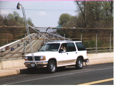
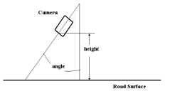
Independent of the camera used the infrared sensor is mounted on a lightweight aluminum monopod and is positioned in a way that the maximum view of the road surface is maintained at all times as illustrated in the Figures 27-3 and 27-4, below. A precision position sensor is mounted at the rear of the vehicle to monitor the position of the camera relative to the bridge at all times. The infrared imager and position sensor is interfaced to a computer for data collection and post analysis of defect areas. The integrated system is easily operated from a van, pickup truck, dump truck, or other vehicle.
The Infrared Bridge Inspection System is easily operated by a single operator and a vehicle driver. The driver positions the vehicle in a defined lane flow pattern as shown in Figure 27-5 below. At the onset of each lane inspection the system operator simply presses a key on the computer keyboard to begin the data collection process. Because the inspection vehicle is moving at speeds of up to 15 MPH, traffic control requirements are greatly reduced relative to traditional sounding inspection techniques.

As the vehicle travels along the lane, the program will automatically create a position based mosaic image of the bridge deck. The system maintains all logistic control functions, keeping track of the bridge being inspected and the lane that is currently being evaluated. All image data, calibration parameters, and descriptive information relating to the bridge are saved in a bridge specific database for future analysis.
After the inspection is completed, the bridge deck image data is further analyzed to identify and mark problem areas. The Infrared Inspection System allows the operator to recall images to screen and outline a shape within the image that is considered an anomaly. Once this area is marked the coordinate positions and size of each anomaly are saved in the bridge database.
A Bridge Map is displayed at any time as a graphic illustration for the bridge under analysis. As part of this map, the delaminations are depicted in their relative position and summary statistical data found per lane is shown. The Infrared Inspection System allows the ability to print a hard-copy Bridge Map as it displays on the screen.
The entire mapping process and data base generation is highly automated, saving valuable time relative to present manual documentation methods. The created database can be re-entered at any time in the future to revisit the data collected, reprint the Bridge Map, and compare subsequent inspections which is important in developing a measure of how the bridge is deteriorating over time.
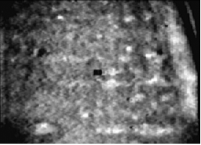
There are several images presented below that illustrate the value IR has in detecting delaminations and other related road deterioration. The results shown are those taken from an actual Infrared Inspection System operational demonstration. Note, as mentioned, the time of day and the weather conditions prevalent both before and during the scanning activity are very important.

It is without question that to address our growing infrastructure problems we must begin to apply and expand technologies currently available to us. The Infrared Inspection System is a bridge inspection and management program that compiles proven, bridge deck relevant, technologies. These technologies are specifically configured and employed to address the bridge deck issues, not only from an inspection perspective, but from a management perspective as well. The potential for inspection time-savings is enormous and the knowledge generated through the use of this program provides valuable information for the ongoing and future management of our country’s bridge systems.
Infrared Cameras Inc. is a leader in infrared technology for pavement inspection. Take a look at our cameras specifically designed to work with all types of buildings and infrastructures at infraredcameras.com.
You can also read the full post at: PaveMan Pro.com


